DIFFERENTIAL PAIR SETUP
Introduction
Routing a differential pair on the layout first requires setup and configuration of the differential pair both on the schematic and in the design rule system on the layout. This topic covers all of the general setup requirements that enables you to route differential pairs in Proteus.
See Also:
Example: Routing a simple differential pair on one layer.
Example: Routing a differential pair with vias / fanout.
Example: Routing a differential pair through a passive component.
Example: Routing a differential pair with taps / branches to passives.
Schematic Setup
On the schematic there are two tasks required for a diff pair, namely to identify the differential pair pins and then to name the diff pair itself. Both of these are done with the diff pair configurator tool which is launched from the right click context menu on one of the two diff pair wires.
The schematic side of this is also covered in the Schematic Capture reference manual.
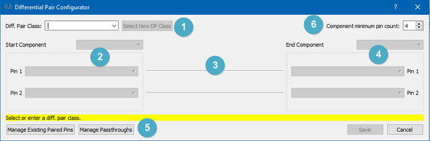
The differential Pair Configurator when opened.
1. Diff Pair Class.
Name of the diff pair class. This is used when setting clearances and separations for the diff pair. Can use an existing one if , for example, you have multiple channels.
2. Start Component.
The start component and the two diff pair pins on the start component.
3. Signal Path Indicator
Shows whether the diff pair signal path is completely specified from source to destination.
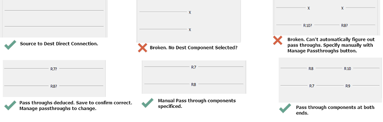
Examples of how the Signal Path Graphics inform you of configuration progress.
4. End Component.
The end component and the two diff pair pins on that component.
5. Manage Pass through components.
Manually specify pass through components if the heuristic fails to do it correctly. A deduced pass through will be suffixed with a question mark. If correct save will commit, if incorrect specify manually via the Manage Passthroughs button.
A pass through has 2 pins on at least one of the diff pair lines. A tap, branch or shunt is not a pass through component and will be ignored by the configurator. The goal of managing the passthroughs is to specify the two pins of the component that are on the line, a simple task for a two pin passive but possibly needing manual specification for a 4-pin part spanning both lines.
6. Component pin count.
Since the start and end component are unlikely to be 2 pin devices this setting serves only to remove the clutter from the component pin listings.
Workflow :
This workflow assumes everything is placed and wired on the schematic. Make sure your connections are made with terminals and terminal labels and not junction dots and wire labels.
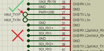
Use terminals and terminal names, not junction dots and wire labels.
- Name the diff pair class.
- Find the start component.
- Find the end component.
- Select the start component pins.
- Select the end component pins (if not done automatically)
- Manage the pass through components (if not done automatically)
- Save and exit when the configurator dialogue shows a complete signal path.
Start and End Components
Right click on one of the diff pair lines and select the diff pair configurator from the resulting context menu.
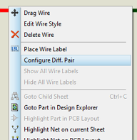
Launch the configurator from the context menu on one of the diff pair wires.
At the top, give the diff pair a class name or select an existing one. It's quite possible to have multiple diff pairs sharing the same class and this can be helpful when setting up diff pair routing rules on the layout. Next, select the start component and the end component.
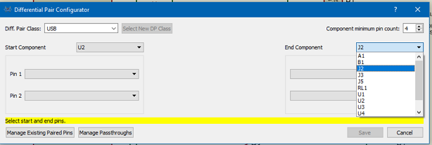
Find the start and end components.
Start and End Pins
Next, select the two pins on the start component that form the differential pair.
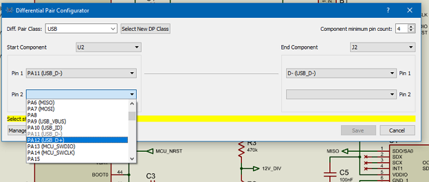
If there are no passthrough components the end pins will populate automatically as you specify the start pins.
If there are no pass through components then the end component and pins should appear automatically and you can simply exit the dialogue form. If there are other components on the net the configurator will try to add them to the signal path along with the corresponding destination pin. Any pass through that the configurator adds will be suffixed with a question mark.
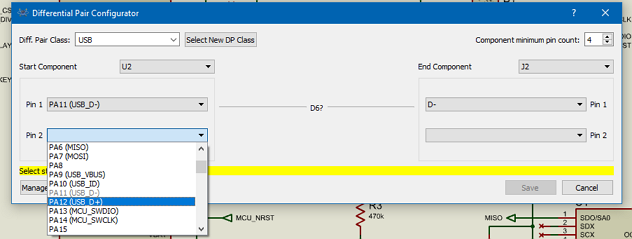
The configurator scans for pass through components.
If the pass through components are correct (and they usually will be) you don't need to do anything else and can simply save and exit the configurator when you are finished specifying the pins. If however, the pass through components are not correct or it's a single component with a lot of pins then you'll need to manage the pass through manually.
Add Pass Through Components
A pass-through component is one which has two pins on the same diff pair line (that the signal passes through). Sometimes, these have to be added manually to complete the signal path for the differential pair. Do this using the Manage Passthroughs button at the bottom of the configurator.
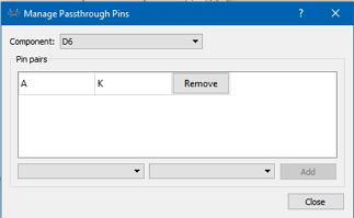
Specifying a placed and wired diode as a pass through component on a diff pair line.
Normally, you'll either be adding one component twice with different pins
(e.g. a 4-pin component sitting across the pair) or two components with
their pins as shown below.
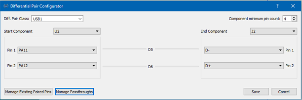
Both diodes have been specified as pass-throughs and the signal path from source to receiver is complete.
Notice that the pass through components are not suffixed with a question mark because they have been added manually rather than deduced from the net topology.
It's possible to have pass through components on the diff pair at both ends in which case you just need to add them one by one to the configurator.
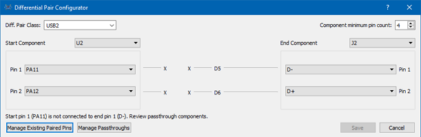
Pass through components on the other side still to be added, back to the Manage Passthroughs button.
Adding all of the pass through components results once again in a completed signal path from source to receiver.
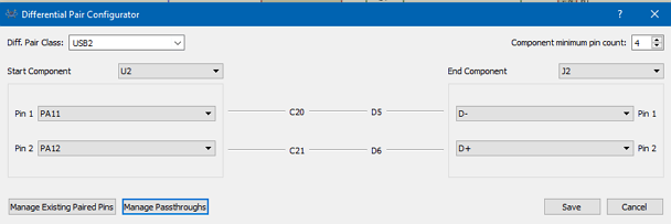
All pass through components added, complete signal path shown. Save and Exit.
A branch or a tap or a shunt is not a pass-through. For example, if there were resistors to ground they would not affect the signal path and the configurator could be exited directly after setting the end component.
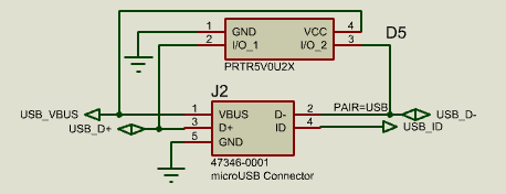
This ESD Protection device is NOT a passthrough component: only one pin per line.
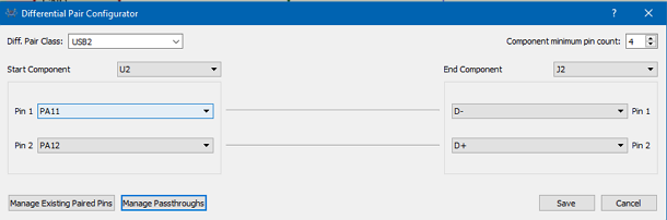
Complete signal path with no pass through components on the diff pair lines.
Setting up pass through components allows the diff pair to be treated as a single entity from start pin to finish pin in terms of length matching.
See Also:
Example: Routing a differential pair through a passive component.
Net Class Setup
After the schematic setup is complete we are into the design rule manager on the layout module (Technology Menu).
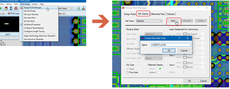
Creating a new Net Class for the Differential Pair
We want to create a new net class so that we can:
- Specify routing styles such as track widths.
- Create specific design rules which we can apply only to the net class (the rules themselves are created at a later stage).
After setting the routing styles as required switch to the differential pair tab, select the correct diff pair and assign the net class to the diff pair.
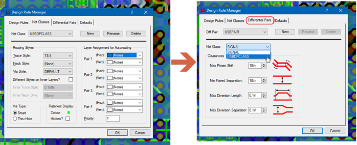
Assigning the configured Net Class to the Differential Pair.
Note that unlike the normal assigning of a net class (with a wire label) all you need to do for a diff pair is set the net class on the dialogue form. This is because Proteus already knows about the wires via the setting of the PAIR name. This system allows you to configure one net class / design rule set and apply it to multiple differential pairs.
If you leave a differential pair with no net class assigned it is not left unconstrained: the pair falls back to the SIGNAL net class and routes with the styles and rules defined there. Assigning a net class of your own is therefore about taking control of the track widths, via styles and rules for the pair rather than about enabling them in the first place.
You may find it useful to change the ratsnest colour for the differential pairs in the net class tab. This will make them easier to find on the layout and, since they'll typically be routed early it's helpful to distinguish them from other connections.
Differential Pair Setup
The Differential Pairs tab contains some extra fields for configuration, arranged in two groups. Clearances holds the two separation values that describe how far apart the two tracks of the pair may sit, and carries the reminder that these are separations between this differential pair and other traces. Tolerances holds the limits that Proteus tests against: the phase shift it will accept before correcting, the unpaired length it will accept, the length match tolerance for the pair as a whole, and the Correct phase shift at end option that decides where the phase correction is placed.

The Differential Pairs tab of the Design Rule Manager.
Min Paired Separation 
This is the minimum (and also preferred) distance between the two tracks. Any increase from this distance would be considered unpaired and can happen either due to phase match serpentine segments or at the start and end of the routes while making connections to the pads. This value is used by the assisted routing mode to apply the separation between the two tracks. It is also used in the reporting to indicate when tracks may be uncoupled and the Pre-Production checker uses this value to test for compliance.
Note however that this is not automatically made into a design rule. We set up a specific design rule for this manually in the next section.
Max Unpaired Separation 
This is the maximum distance between the two tracks that is allowed at any time.
Note that this affects the ability of the differential pair to phase match because it constrains the maximum height of a serpentine segment.
Max Phase Shift 
Differential pairs are length matched against each other but this length matching cannot just be done at any time. To keep differential signals opposite you want to equalise the track lengths as soon as possible after they deviate.
Phase shift (sometimes called skew) is when the lengths of the two tracks becomes different. This typically happens when you change direction because the track on the outside of the corner traverses more distance during the change of direction. Fortunately, Proteus knows the lengths of both tracks and will automatically add serpentine segments to equalise their lengths when you finish placing the route.
Max Phase Shift is the allowable difference in track length due to a diversion or corner before serpentine routing is applied to one track to equalise their lengths.
It's important to understand that any corrective action (adding serpentine segments) can only be considered at the end of a corner or diversion. It's quite possible with a large curved corner therefore for the lengths of the two tracks to become significantly different before any serpentine is applied to correct their lengths.
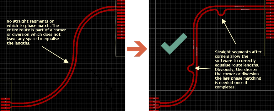
Proteus can only equalise lengths on straight segments of track after a corner or diversion.
The equalising of routes is done post process, not during routing so you'll see it after you commit route placement.
See Also:
Length Match Tolerance 
This is the tolerance to which differential pairs must be matched against either a target length or a second differential pair. It has nothing to do with the matching of the lengths of the two tracks in a differential pair to each other which is covered by the phase matching tolerance field above.
See Also:
Example: Length Matching a Differential Pair
Max Unpaired Length 
This is the maximum distance that is allowed for any deviation from the paired separation.
This value is checked in the differential pairs report and in the pre-production checker but is not used to constrain the phase matching. While unlikely, it is possible therefore that required phase matching breaches this distance. Should this happen you need to review the topology of the route (how many corners and how severe they are) to reduce the necessary phase matching.
Correct phase shift at end
With this option clear, Proteus corrects the phase at the end of each corner, so a route with several corners ends up with several small serpentines spread along it. Tick it and the correction is instead gathered into a single serpentine at the end of the route. Which you want depends on the application: correcting as you go keeps the out of phase distance short, while correcting at the end keeps the body of the route clean.
See Also:
The shape and size of the serpentines Proteus uses for both phase matching and length matching the pair are set separately, with the Technology Menu > Configure Length Matching command.
See Also:
Design Rule Setup
Now we can switch to the rule tab of the Design Rule Manager to set up any additional constraints that we want to apply to the diff pair. There are two rules which we would almost always set up:
- A rule to ensure adequate clearance from all other objects and the diff pair.
- A rule to enforce the clearance between the two tracks. This should be set to the paired distance value entered in the diff pairs tab.
We create a new rule and use the net class we created to narrow the scope of the rule to only the diff pair. Then in the first case we would set it to apply with respect all other net classes. This gives us clearances between the diff pair and everything else that we can set from the fields on the right hand side.
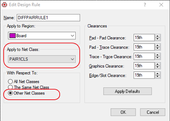
Creating a Design Rule to apply to the Diff Pair net class with respect other net classes (case 1 ).
You often want to limit the region of this rule to a particular layer. This allows you to set wide separation to other objects (e.g 3->5 x trace width) on the routing layer while not causing DRC errors on the fanout stubs from the source/destination pins.
For the second rule we again apply to the diff pair net class but this time we set it to apply to the same net class. This lets us set clearances between the two tracks of the diff pair and so of course we want to insert the clearance value we set for paired separation as the trace -> trace clearance.
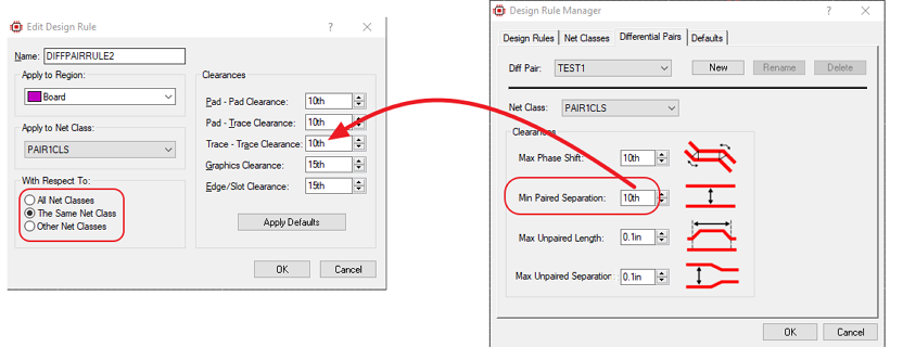
Now creating a rule to set the clearance between the two tracks in the differential pair (Case 2). The Trace-Trace clearance is the paired separation value.
One of the benefits of working through these preparatory steps (create net class -> assign to diff pair -> create design rules) is that one net class can be used for multiple diff pairs (E.g. multiple DDR4 channels). In this case we would simply assign the same net class to each diff pair. Our created design rule would then apply to them all saving quite a bit of setup.